Inside the Loop: Simulating a Toroidal Rotor from Design to Flow
What happens when curiosity loops back on itself — quite literally? At Basma-Tech, we set out to explore a geometry that has recently captured the imagination of both engineers and hobbyists: the toroidal rotor. Unlike conventional propellers that shed energy at their tips, the toroidal design closes the loop — creating a smooth, continuous ring of motion that promises quieter operation and potentially higher efficiency.
Recent research from MIT Lincoln Laboratory demonstrated just how transformative this shape can be. Their experiments showed that a toroidal propeller can significantly reduce noise by disrupting the tip vortices that typically generate the high-pitched whine of traditional propellers [¹]. This discovery has opened an entirely new frontier for compact drone propulsion — and perhaps for hydrodynamic systems as well.
But as with every new concept, the gap between promise and proof can be wide. The process of balancing performance and noise reduction in this still-young design space can be both complex and costly if approached through trial and error alone. What if, instead, we could simulate these interactions digitally — testing geometries, tuning parameters, and building intuition before a single prototype spins? That’s where computational modeling becomes a game-changer. By using simulation, we can parametrically realize new variations of the toroidal concept and understand how subtle design shifts affect flow and sound.
To begin that journey, we needed a baseline model — a digital testbed to help us see, quite literally, how air behaves when the loop closes.
From CAD to Simulaton?
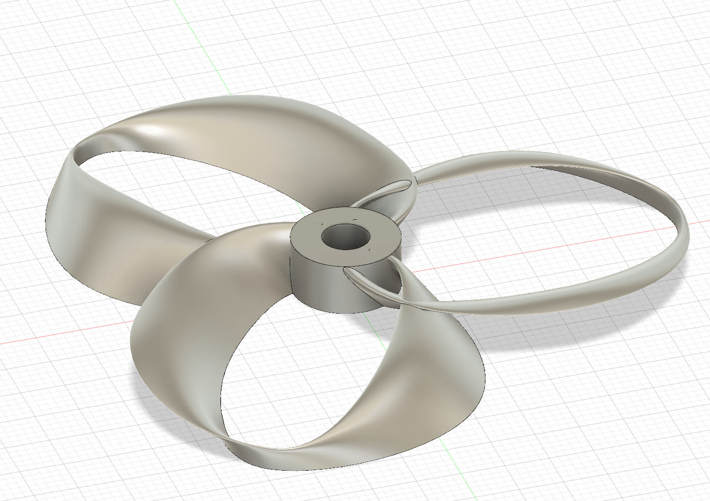
1.What Is a Toroidal Rotor? That’s the essence of a toroidal rotor — a closed-loop propeller designed to keep the swirling tip vortices from spilling out into the air (or water) around it.
In conventional rotors, these vortices trail off each blade tip like miniature tornadoes, wasting energy and generating the familiar high-pitched whine. By looping the tips into a continuous path, the toroidal design helps those vortices cancel or merge within the ring, softening both their noise and their drag.
From an aerodynamic standpoint, it’s a clever redistribution of the same physics that govern lift and induced drag: the loop confines circulation, recycles flow, and reduces losses at the edge. From a practical standpoint, it’s a new balancing act — the geometry is harder to manufacture, and its internal flows are more complex to predict. That complexity is what makes simulation so valuable: every subtle curve, thickness change, or twist in the loop shifts the way air attaches and detaches from the surface.
Interestingly, the same principle extends naturally to hydrodynamics. Water and air share many flow behaviors, and a toroidal impeller or thruster could exploit the same closed-loop efficiency for underwater vehicles or pumps. By studying it in air first, we gain an early glimpse into how the shape might perform in denser fluids — and how parameters such as curvature, pitch, and ring ratio could translate across domains.
Before we could run any of those comparisons, we needed a reliable digital baseline — a clean 3D model that captures the essential geometry and symmetry of the rotor. That model became the starting point for everything that followed: the sketches, lofts, and patterns that would soon transform into our first simulated flow.
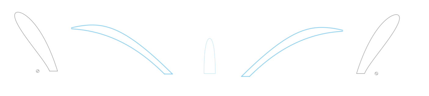
2.From Sketch to Shape — Building the Model Creating the toroidal rotor begins not with equations, but with sketches — a few carefully shaped cross-sections that define the entire loop. While the aerodynamic concept follows the geometric principles outlined in Wei et al., 2024 [1], the hands-on process of translating that theory into a solid model drew heavily from the meticulous Fusion 360 tutorial by STRIKING FPV [2]. Their step-by-step demonstration offered one of the clearest and most thoughtful visualizations of how to build this complex form from scratch.
n our case, the design starts with three key cross-sections that describe the airfoil’s curvature: an inner ring, a mid-profile, and an outer edge. Together, these sketches shape the continuous torus when connected through a circular trajectory. The principle is simple but delicate — each section must blend seamlessly into the next so that the resulting surface carries a smooth aerodynamic contour.
Following the approach shown in the STRIKING FPV tutorial, we aligned the sketches along the sweep path and used Fusion 360’s Loft tool to form the closed loop. Small adjustments to twist or spacing subtly affect how the loop “breathes” as it rotates, so several iterations were explored before arriving at the final geometry.
This stage isn’t about formulae — it’s about geometric intuition. The goal was to achieve a clean, watertight body suitable for CFD, while preserving the toroidal symmetry and flow continuity that make this design so visually striking.
The geometric framework of this rotor follows the description by Wei et al. (2024) [1], while the practical modeling process was inspired by the detailed Fusion 360 workflow demonstrated by STRIKING FPV [2]. Their video remains one of the most accessible and well-explained guides to toroidal rotor construction available online.